Schematics and functional diagrams

From Design to Reality: The Strategic Role of Representation

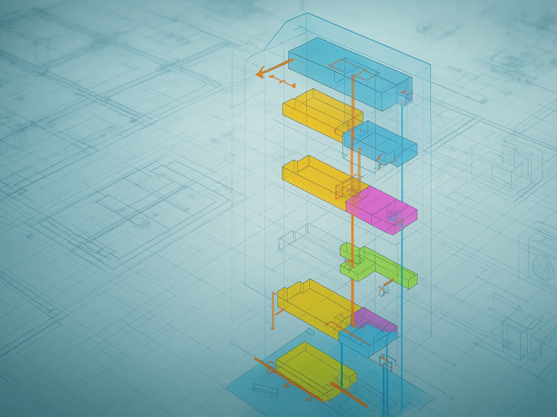
In the building design process, the graphical representation of technological and plant systems through functional diagrams and schematics plays a crucial role. These tools are not merely visual representations but actual logical and technical models that allow for understanding, coordinating, and controlling the operation of the various components of a building.

Their importance becomes particularly evident in detailed executive design, where the accuracy and completeness of information are essential to ensure that the project can be translated into an executable, safe, and high-performing work. Functional diagrams and schematics reduce ambiguity, facilitate interdisciplinary collaboration, and support both the construction and maintenance and management phases of the building.

Definition and Characteristics

Functional schematics are simplified graphical representations that describe the behavior and interconnections of plant and technological systems. Functional diagrams, on the other hand, emphasize the operational logic of processes, illustrating the flows of energy, fluids, or information within a system.

Main Characteristics:

  • Clarity: immediate representation of the relationships between components.
  • Precision: use of standardized symbols (UNI, ISO, IEC).
  • Multidisciplinarity: applicable to various fields, from electrical systems to thermomechanical systems, up to acoustic and environmental management.
  • Scalability: level of detail adaptable according to the design phase.

Types of Functional Schematics and Diagrams

1. Single-line and multi-line electrical schematics
  • They represent the distribution of electrical energy.
  • They specify electrical panels, protections, cable sections, and safety devices.
  • They describe hydronic circuits, ventilation networks, and air conditioning systems.
  • They indicate valves, pumps, exchangers, and control sensors.
  • Logical diagrams for the integrated management of HVAC, lighting, security, and special systems.
  • They show sensors, actuators, and control logics.
  • Functional representations of sound propagation paths.
  • Used to design acoustic mitigation interventions and improve indoor comfort.
  • Typical diagrams of industrial design adapted to the building context (P&ID – Piping and Instrumentation Diagram).
  • They represent lines, equipment, and instrumentation with functional detail.

Functions of Functional Schematics and Diagrams

1. Design Support
  • They allow designers to verify the logical and technical consistency of the system.
  • They facilitate the selection of the most suitable materials and equipment.
  • They reduce conflicts between disciplines thanks to a shared vision of system operation.
  • They promote the detection of interferences and their preventive resolution.
  • They guide the practical execution of the systems.
  • They offer a unique technical language for installers, project managers, and suppliers.
  • Schematics and diagrams are used for diagnostics, predictive maintenance, and corrective interventions.

Supporting technologies

  • BIM (Building Information Modeling): association of functional schematics with 3D models of the systems, enriched with technical and logical data.
  • Advanced CAD Software: creation of standardized schematics with standard symbols.
  • Simulation Platforms: integration with thermo-fluid dynamic calculations and energy simulations.
  • Augmented Reality: overlay of functional schematics on real spaces to facilitate installations and maintenance.

Benefits of Using Functional Schematics and Diagrams

1. Error reduction
  • Elimination of ambiguities and misinterpretations.
  • Acceleration of executive phases thanks to immediate and standardized representations.
  • Better verification of system performance against design requirements.
  • Possibility to optimize consumption and environmental performance thanks to schematics that highlight inefficiencies.
  • Documentation consultable throughout the building’s lifecycle.

Challenges and issues

  • System Complexity: the increasing integration between systems requires increasingly complex schematics.
  • Dynamic Updating: need to keep schematics updated in the face of design changes or ongoing variations.
  • Standardization: use of non-uniform symbols can create interpretative difficulties.
  • Specialist Skills: development and reading require trained and multidisciplinary personnel.

Integration into the construction cycle

Functional schematics and diagrams accompany all project phases:

  • Design: logical and functional definition of systems.
  • Construction: operational guide for installations and verifications.
  • Testing: comparison between theoretical schematics and actual operation.
  • Management: tool for building maintenance and upgrading.

Functional schematics and diagrams are essential tools in detailed executive design, as they allow complex design concepts to be transformed into clear, shareable, and operational representations. Their adoption reduces risks, optimizes time, and improves the overall quality of the work.

Thanks to integration with modern digital technologies, these tools are no longer just static elaborations but become part of a dynamic ecosystem that supports design, construction, and management. Ultimately, investing in the accurate production of functional schematics and diagrams ensures technical reliability, execution efficiency, and long-term sustainability of building works.

Segui i nostri profili social
Privacy Overview

This website uses cookies so that we can provide you with the best user experience possible. Cookie information is stored in your browser and performs functions such as recognising you when you return to our website and helping our team to understand which sections of the website you find most interesting and useful.